ATtiny2313からTC1602E-13Aを使ってみます。
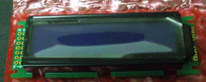
(TC1602E-13A)
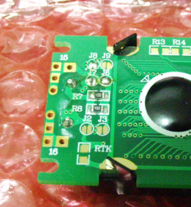
まずは下準備。 コネクタを付けないと使えないです。
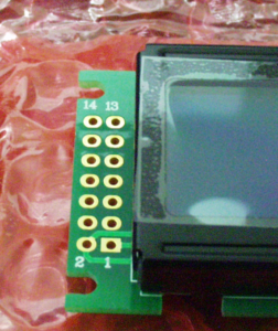 (表) | 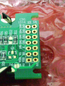 (裏) |
下のようにピンヘッダーを付けました。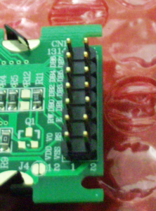
次はバックライトをロジック電源と同一にしたいので、以下のJ2とJ3をハンダ付けして短絡します。
 (短絡前) | 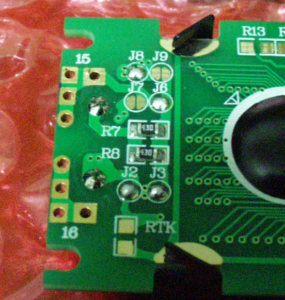 (短絡後) |
ハンダ付けは慣れていないので、上手いとか下手とか分かりませんが、きっと下手だと思います。
下準備ができたら、ブレッドボードを使って、ATtiny2313とTC1602E-13Aを接続します。
接続図は、bread.shが使えそうでしたので、試みましたが、こんなひどい図になってしまいました。やはり斜めのワイヤーを直線で引くと見難いですね。そのうち直します。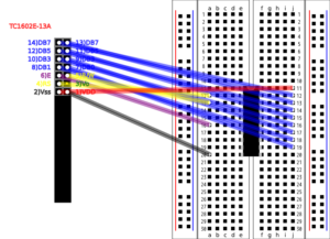
仕方なくlibreOfficeで書いた接続図です。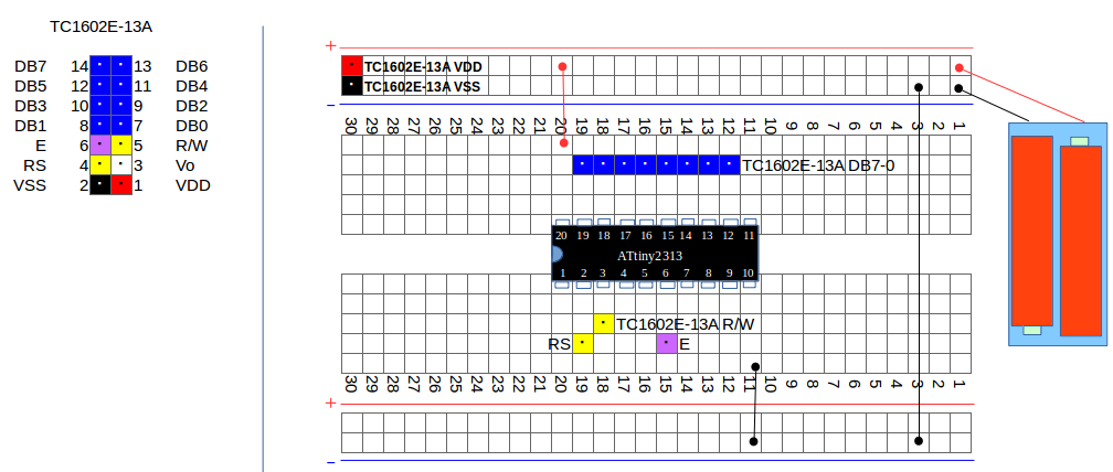
LCDへコマンドを送るのは、EをHにしてLにすれば良いです。つまり、Eは、PORTDの2に割り当ててあるので、コマンドを送信するには、
PORTD |= 0b00000100;
で、PD2をHにして、
PORTD &= ~0b00000100;
で、PD2をLにすれば良いことになります。
TC1602Eのマニュアルによると、EのHしてLにする時間は、最低でも450ナノ秒必要ですので、ざっくり1マイクロ秒をウェイト(_delay_us(1))で入れています。ただし、CPUクロックは1MHzで動作していますので、1命令実行すれば1usぐらいは経過します。他MPUで動かす場合の保険として入れておきます。
プログラムはこんな風になりました。学習のためのプログラムなので、あえて関数化やマクロ化はしてません。
~$ cat -n test.c
     1	#include <avr/io.h>
     2	#include <util/delay.h>
     3
     4	int main(void)
     5	{
     6		DDRB = 0b11111111;      //ATtiny2313 pin.12-19 PB0-7 OUT
     7		DDRD = 0b00000111;      //ATtiny2313 pin.2,3,6 PD0-2 OUT
     8
     9		PORTD = 0b00000000;	//RS(PD0)=L,R/W(PD1)=L,E(PD2)=L
    10
    11		// After power on
    12		_delay_ms(41);
    13
    14		// Function Set(8bit mode) 1st
    15		PORTB = 0b00111000;
    16		PORTD = 0b00000000;	//RS(PD0)=L R/W(PD1)=L
    17		_delay_us(1);
    18		PORTD = 0b00000100;	//E(PD2)=H
    19		_delay_us(1);
    20		PORTD = 0b00000000;	//E(PD2)=L
    21		_delay_ms(5);		//more than 4.1ms
    22
    23		// Function Set(8bit mode) 2nd
    24		PORTD = 0b00000100;	//E(PD2)=H
    25		_delay_us(1);
    26		PORTD = 0b00000000;	//E(PD2)=L
    27		_delay_us(100);		//more than 100us
    28
    29		// Function Set(8bit mode) 3rd
    30		PORTD = 0b00000100;	//E(PD2)=H
    31		_delay_us(1);
    32		PORTD = 0b00000000;	//E(PD2)=L
    33		_delay_us(40);		//more than 38us
    34
    35		// Function Set(Rows and Fonts)
    36		PORTB = 0b00110100;
    37		_delay_us(1);
    38		PORTD = 0b00000100;	//E(PD2)=H
    39		_delay_us(1);
    40		PORTD = 0b00000000;	//E(PD2)=L
    41		_delay_us(40);		//more than 38us
    42
    43		// Display OFF
    44		PORTB = 0b00001000;
    45		_delay_us(1);
    46		PORTD = 0b00000100;	//E=1(PD2)=H
    47		_delay_us(1);
    48		PORTD = 0b00000000;	//E=0(PD2)=L
    49		_delay_us(40);		//more than 38us
    50
    51		// Clear Display
    52		PORTB = 0b00000001;
    53		_delay_us(1);
    54		PORTD = 0b00000100;	//E=1(PD2)=H
    55		_delay_us(1);
    56		PORTD = 0b00000000;	//E=0(PD2)=L
    57		_delay_ms(2);		//more than 1.52ms
    58
    59		// Entry Mode Set(Cursor and Shift)
    60		PORTB = 0b00000110;
    61		_delay_us(1);
    62		PORTD = 0b00000100;	//E=1(PD2)=H
    63		_delay_us(1);
    64		PORTD = 0b00000000;	//E=0(PD2)=L
    65		_delay_us(40);		//more than 38us
    66
    67		// Display ON
    68		PORTB = 0b00001111;
    69		_delay_us(1);
    70		PORTD = 0b00000100;	//E=1(PD2)=H
    71		_delay_us(1);
    72		PORTD = 0b00000000;	//E=0(PD2)=L
    73		_delay_us(40);		//more than 38us
    74
    75		// Write Data
    76		PORTB = 'H';
    77		PORTD = 0b00000001;	//RS(PD0)=H
    78		_delay_us(1);
    79		PORTD = 0b00000101;	//RS(PD0)=H,E(PD2)=H
    80		_delay_us(1);
    81		PORTD = 0b00000001;	//RS(PD0)=H,E(PD2)=L
    82		_delay_us(40);		//more than 38us
    83
    84		// Write Data
    85		PORTB = 'E';
    86		PORTD = 0b00000001;	//RS(PD0)=H
    87		_delay_us(1);
    88		PORTD = 0b00000101;	//RS(PD0)=H,E(PD2)=H
    89		_delay_us(1);
    90		PORTD = 0b00000001;	//RS(PD0)=H,E(PD2)=L
    91		_delay_us(40);		//more than 38us
    92
    93		// Write Data
    94		PORTB = 'L';
    95		PORTD = 0b00000001;	//RS(PD0)=H
    96		PORTD = 0b00000101;	//RS(PD0)=H,E(PD2)=H
    97		_delay_us(1);
    98		PORTD = 0b00000001;	//RS(PD0)=H,E(PD2)=L
    99		_delay_us(40);		//more than 38us
   100
   101		// Write Data
   102		PORTB = 'L';
   103		PORTD = 0b00000001;	//RS(PD0)=H
   104		PORTD = 0b00000101;	//RS(PD0)=H,E(PD2)=H
   105		_delay_us(1);
   106		PORTD = 0b00000001;	//RS(PD0)=H,E(PD2)=L
   107		_delay_us(40);		//more than 38us
   108
   109		// Write Data
   110		PORTB = 'O';
   111		PORTD = 0b00000001;	//RS(PD0)=H
   112		PORTD = 0b00000101;	//RS(PD0)=H,E(PD2)=H
   113		_delay_us(1);
   114		PORTD = 0b00000001;	//RS(PD0)=H,E(PD2)=L
   115		_delay_us(40);		//more than 38us
   116
   117		while(1)
   118			;
   119
   120		return 0;
   121	}
写りが悪いですが、このように表示されます。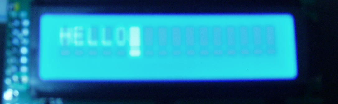
※ソースはgithubに登録してます。
takk@deb83:~$ git clone https://github.com/takkete/bread.git
Cloning into 'bread'...
remote: Counting objects: 52, done.
remote: Compressing objects: 100% (29/29), done.
remote: Total 52 (delta 7), reused 0 (delta 0), pack-reused 17
Unpacking objects: 100% (52/52), done.
Checking connectivity... done.
takk@deb83:~$ cd bread/mcu/avr/attiny2313/device/tc1602e-13a/
takk@deb83:~/bread/mcu/avr/attiny2313/device/tc1602e-13a$ make

コメント
[…] 前回「AVRからPORT制御のLCDを使う(ATtiny2313,TC1602E-13A)」で、8BITモードで使用したキャラクタLCDですが、今回は4BITモードで使います。 […]